

Cladding installation and maintenance
How does wind load affect support spacing for sandwich panel walls?
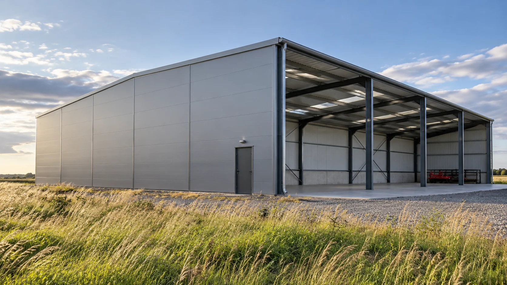
To select support spacing for sandwich panel walls, start with the wind pressure and suction on each part of the façade. Loads vary with the site, surrounding terrain, building height and shape. Corners and edges need separate consideration, and openings can affect internal pressure. Check the span table for the exact panel facings, support arrangement, fixings and permissible deflection. When recladding, measure the existing frame. For a new building, plan the openings and allow for intended alterations. A layout used on a low building nearby may be unsuitable for a taller, more exposed wall.
In this guide
How wind loads vary across a façade
The structural designer determines wind pressure and suction for each zone. Suction pulls the cladding away from its supports, placing demand on the fixings. A panel may carry the load over the proposed span while the fastener or the material it is anchored into governs the capacity of the connection.
How the supports affect panel behaviour
A panel spanning between two supports behaves differently from one that runs continuously over an intermediate support. Span tables distinguish between single-span and continuous arrangements and specify the bearing conditions. Read the column for the actual arrangement. Another column may show a longer span that the proposed wall cannot achieve.
Check the bearing width and the geometry of each connection as well as the distance between support centrelines. A rail can be in the right position yet provide too narrow a bearing face. Before choosing replacement cladding, measure the support faces and spacing on the existing frame.
Choosing the span table for the specified panel
Match the table to the core material, panel thickness, both facings, their profiles and the fixing type. Values for a 0.6 mm steel facing cannot simply be applied to a 0.5 mm version. Changing the facing can affect load capacity, stiffness and local behaviour at the support.
Read the table notes to see whether the figures are characteristic loads, design values or another quantity, and which criteria apply. Put the loads and tabulated values on the same basis before comparing them. If the basis is unclear, ask the structural designer to interpret the data.
Checking deflection and temperature effects
Load capacity and serviceability are separate checks. A panel may carry the specified load yet deflect more than the wall detail allows. Excessive deflection can affect the façade’s appearance, strain joints and interfere with adjacent windows or doors.
The colour of the outer facing affects how much it heats up in sunlight. Span tables may therefore specify colour groups and length limits. If the finish changes from light to dark, check that the proposed panel length and support arrangement still fall within the permitted range.

How openings and fire resistance can limit the span
Windows and loading doors interrupt the panel and support layout. They need suitable framing and fixings around their edges. Even when wind loading would permit the longest span in the table, the opening detail may require closer supports.
The scope of the wall’s fire resistance classification may impose a further limit. An assembly with a specified EI rating may require a particular span, panel orientation and fixing method. The chosen layout must meet these conditions as well as the wind load and deflection requirements.
What a simple wind load calculation tells you
For illustration, a uniform pressure of 0.8 kN/m² acting over 6 m² produces a total force of 4.8 kN. Multiplying pressure by area shows how much force the panel has to transfer. To determine support spacing or screw quantities, the designer must also check the panel and its connections under the applicable design conditions.
Increasing the span increases the loaded area at a given panel width and changes the bending stresses and deflection. Adding screws in proportion to the extra area cannot account for those effects. Where supports are already in place, the assessment may point to a different panel or alterations to the supporting rails.
What the installer needs on the drawing
Show the wind zones, supports, panel direction and fixing pattern on the drawing. Mark local changes around corners and openings. Before installation, inspect the frame and check its alignment. Straighten or correct misaligned rails before fitting the panels.
Keep the drawings and design information after installation. A new loading door, an additional storey or a change to the façade may require the cladding to be checked again. Recording the support spacing gives the designer a reliable starting point for assessing alterations later.
Frequently asked questions
Is there a safe support spacing for every wall panel?
Support spacing depends on the loads, the particular panel, the support arrangement and the connections. Other project requirements, including those around openings and fire-rated walls, can also govern the choice.
Can a panel span further if more screws are fitted?
The fixings and the panel need separate checks. Increasing the fixing count does not remove limits imposed by bending, deflection or the wall assembly’s classification.
7 branches. Materials closer to your project.

Free quote
Materials for your project




You may also find useful…
The cost of an industrial building includes the work needed to run the business inside it. Alongside the frame and cladding, allow…
The same product family can be used for a warehouse roof, a façade sub-structure and a small frame. Cold-formed profiles have a…

A useful supplier review tells you what the customer ordered, whether the materials matched the specification and how the supplier handled questions…
What will it take to put the building to work? A budget based on floor area or panel prices alone can miss…
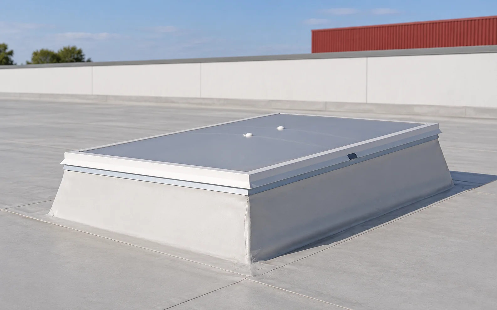
A roof light brings daylight in from above and can help to illuminate the middle of a building. Its area and position…
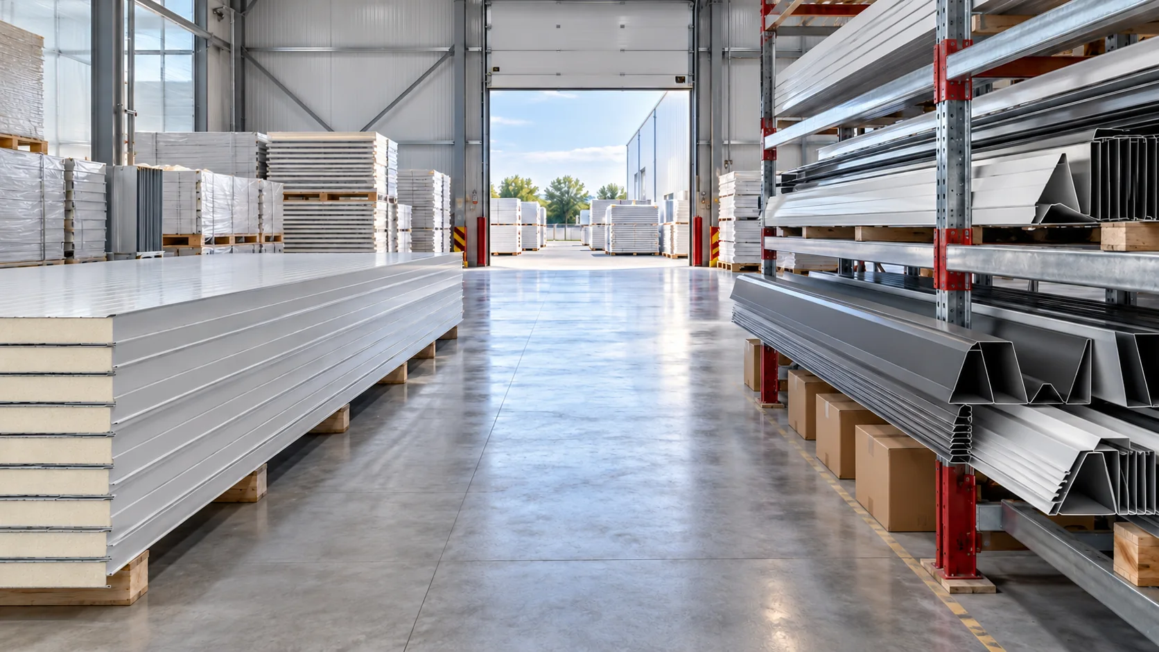
When choosing a supplier for an industrial building envelope, ask them to show how their quotation covers a corner, an opening and…
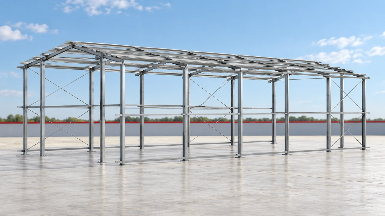
When additional space is needed, the time required to prepare the components matters. Our standard steel structures can be ordered from available…
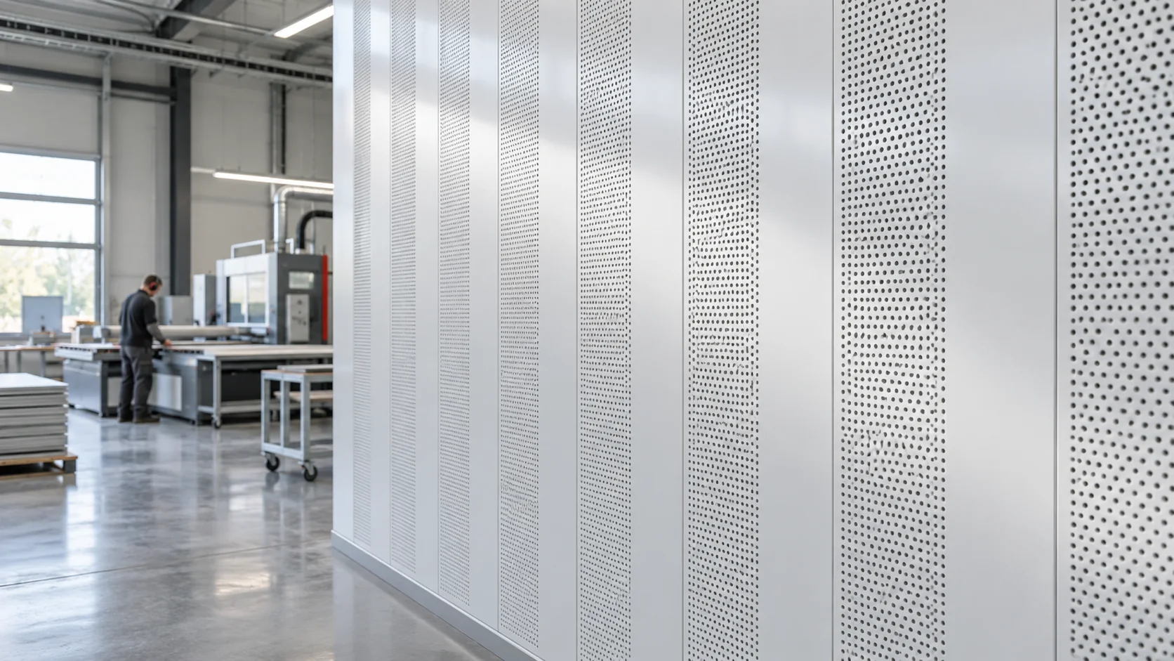
A mineral wool core can help control noise, but the first question is where the sound is causing trouble. If workers struggle…