

Profiles and steel structures
Galvanised channels for steel building walls: simplifying installation
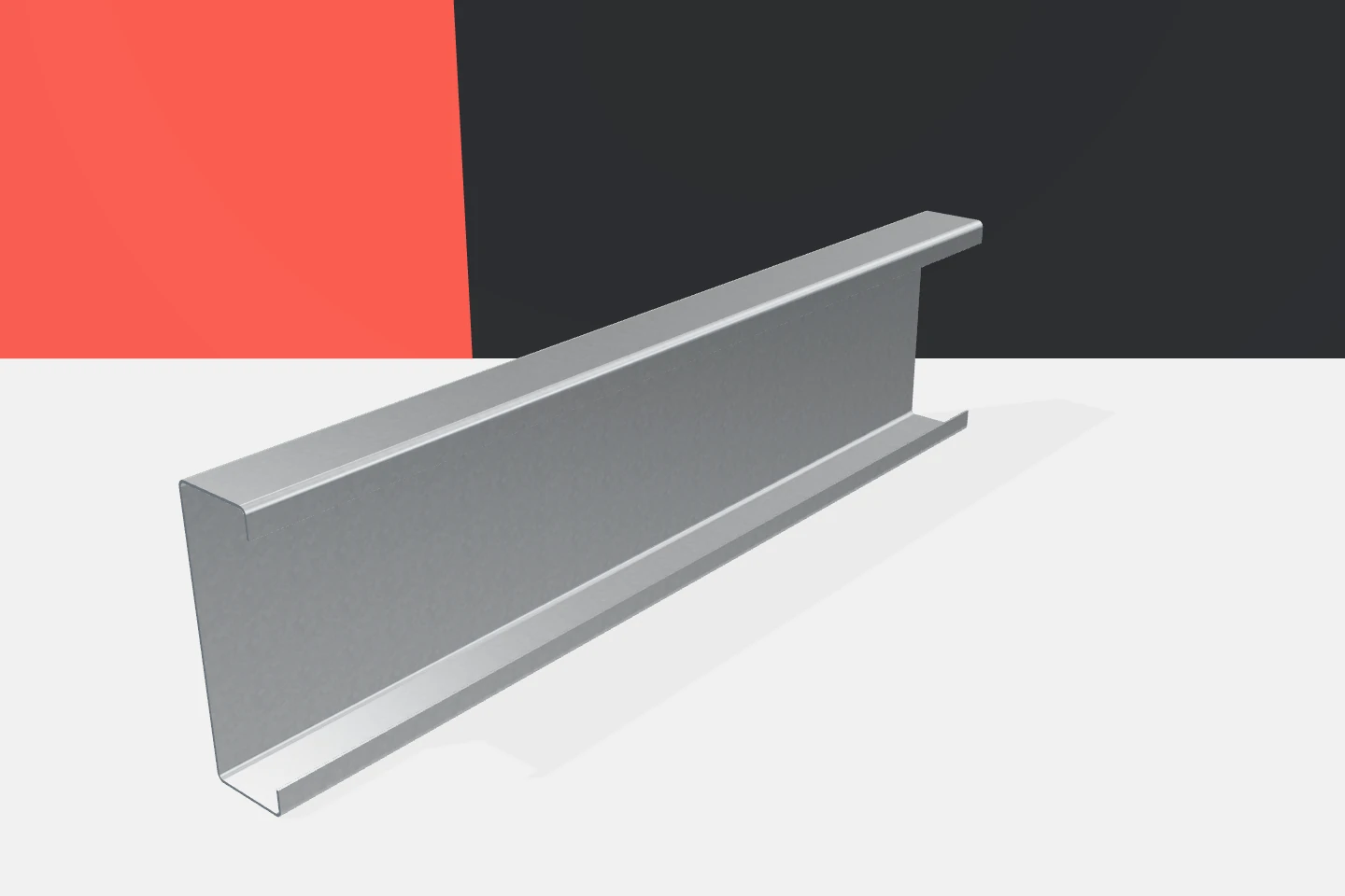
In a hall wall, most unplanned work tends to arise at the details. A rail misses the fixing of the panel, a hole falls beside the gusset plate, and the gate needs an extra beam. Galvanised channel sections allow a repeatable sub-structure to be prepared, but its geometry must be established in advance. Well-documented cold-formed C profiles make installation easier and reduce the cost of alterations. A wall channel section transfers loads from the cladding to the main structure. The arrangement of the rails should correspond to the direction and span of the façade elements. A vertically installed sandwich panel may require a different layout from cladding run horizontally. Before a profile list is produced, a plan for dividing the wall is therefore needed.
In this article
The rail is a support for a specific cladding
The saving from reducing the number of rails may disappear if the cladding has to be changed. It is worth considering both expenditures together. Galvanised profiles are part of a wall system in which the widths of supports, the position of screws and the permissible deflections also matter. A low price for the channel section alone does not resolve these dependencies.
What an open C section provides
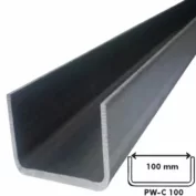
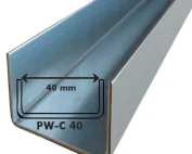
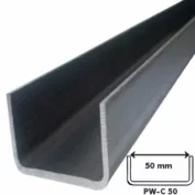
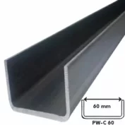
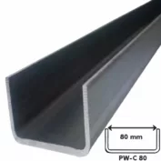
The two flanges of a channel section are on the same side of the web. This makes the section convenient in many connection and framing layouts. In structural profiles, the flanges may end in lips. These small lips are part of the design geometry. They should not be removed or notched to make fitting the cladding easier.
The open shape also means a specific behaviour under torsion. The point of load application is not arbitrary. If the rail is fixed differently from the design assumption, its behaviour may change. The choice of channel section should therefore include the method of support and connection to the column, not only the height and thickness of the steel.
Holes should be established before production begins
Factory hole punching reduces the time spent on setting out and drilling. It also allows repetitive connections to be organised. Each profile should, however, receive an unambiguous drawing with a dimensional datum, end markings and installation direction. Similar right-hand and left-hand components are easily confused when the documentation lacks a clear view.
It is worth checking the channel sections at corners, junctions and openings separately. These are where exceptions to the typical wall rhythm occur. Correcting such places only on site requires additional fabrication and coating inspection. The saving therefore comes not from the perforation itself but from the perforation matching a detail resolved in advance.
One catalogue system provides round holes of 14, 17 and 18 mm diameter and slotted holes of 14 × 26 and 18 × 26 mm. For the slots, the direction of their longer dimension is also specified. This is a useful example of data that should appear on the production drawing; the correct variant follows from the connection design.
Gates and windows interrupt the regular layout
A large opening in the wall changes the run of the cladding supports. The edges of panels and sheets must have proper bearing, and the framing should transfer the intended loads. Not every channel section sufficient as an intermediate rail will be suitable as a lintel. Requirements must be established for the specific opening and the method of fixing its equipment.
The gate structure may also be subject to actions related to its operation. Their extent depends on the device and the installation solution. This must be agreed with the gate supplier and the designer. Cold-formed profiles are well suited to creating orderly details, but they should not be selected by copying an arbitrary section from an adjacent part of the wall.


Deflection matters for appearance and airtightness
A rail may meet the load-bearing requirements and yet deflect too much for a given cladding. Excessive displacements make it difficult to maintain a level surface and correct connection behaviour. The choice of channel section therefore also requires a serviceability check. Limit values are not established solely on the basis of a general description of the steel.
A distinction must also be made between wind pressure and suction. The wall is not loaded in only one direction. Galvanised profiles, screws and brackets must perform across the entire intended range. Individual zones of the building may require different solutions. Standardising all rails is convenient logistically but should result from a conscious design decision.
Moisture conditions begin at the detail
The zinc coating helps protect the steel but does not eliminate the problem of water retained in the connection. It is worth checking whether the wall geometry allows moisture to drain away and whether critical points will be accessible for inspection. In buildings with elevated humidity, the protection requirements may differ from those in a dry room.
Channel sections should be stored in accordance with the recommendations for the particular product. A pack with water trapped between the profiles is not a correct way to store galvanised material. Inspection after unloading allows damage to be detected before the component goes high up on the façade. This is simpler than repairs carried out after the cladding is closed.
The component list should follow the sequence of work
A good schedule separates typical, corner, eaves and opening-framing rails. Alongside the length, it gives the section, thickness, material and drawing number. It allows fasteners to be counted and deliveries to be prepared according to installation stages. Less time is then spent searching for the right channel section among similar lengths.
Z sections and sigma profiles may also occur in the sub-structure, depending on the adopted solution. Omegas are often used as an additional grid for claddings. Any substitution, however, requires the detail to be checked. The most practical choice of cold-formed profiles is one that combines the required parameters with simple installation and clear documentation.
7 branches. Materials closer to your project.

Free quote
Materials for your project
You may also find useful…
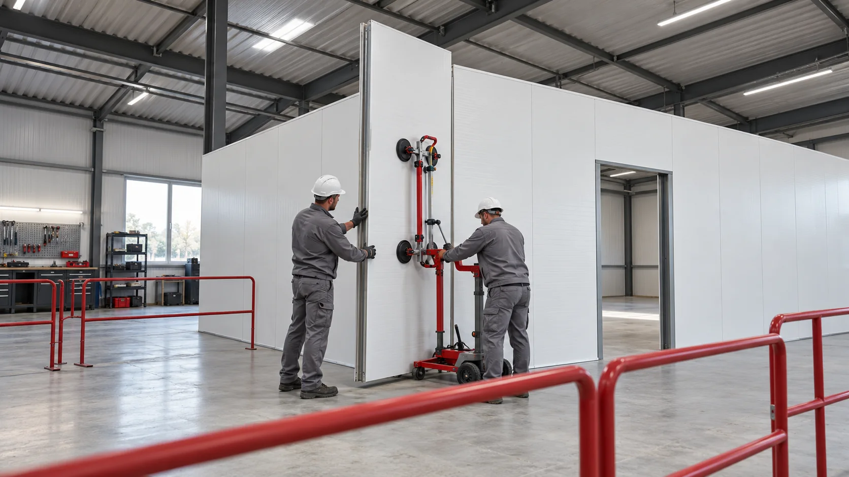
Plan the corners, openings and service penetrations before measuring for sandwich panels. Agree who will erect the frame, fit the panels, install…
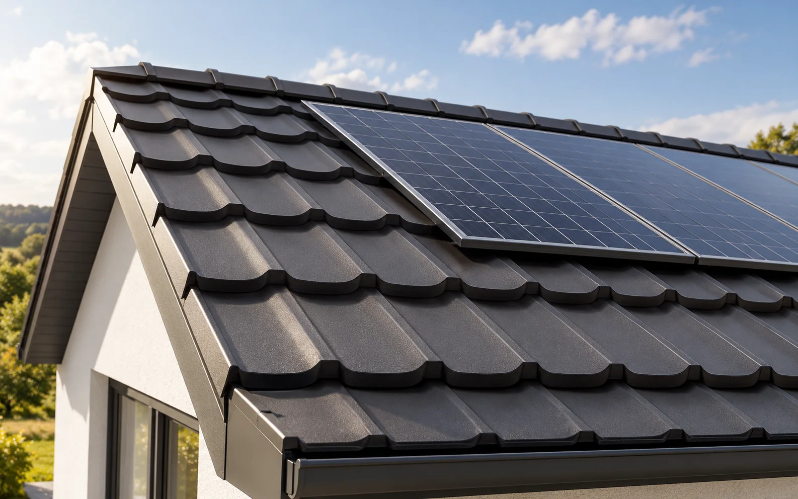
Photovoltaic panels on an existing metal roof require fixings that have been verified for exactly the sheet or sandwich panel installed on…
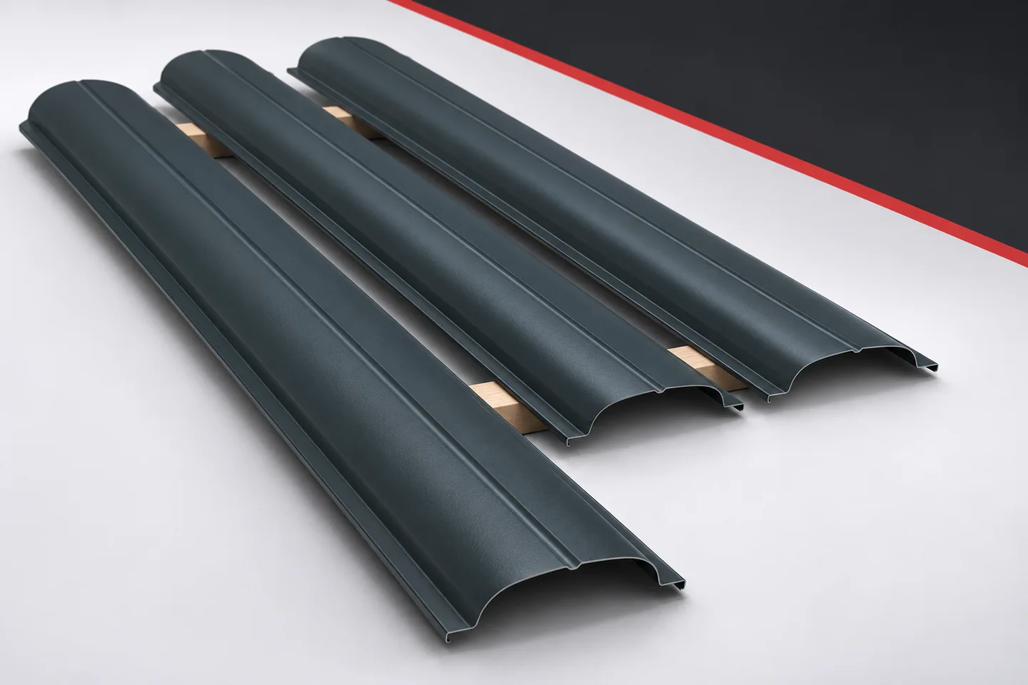
Changing the layout of a plot does not always mean the whole fence has to be thrown away. Some slats can be…
The answer to the question of insulating a loft before installing the lining comes down to the correct sequence of work and…
Installation of modular metal roof tiles begins with a level substructure, the correct layer sequence and a properly formed eaves zone. Only…
A rainwater gully (downpipe leaf catcher) is usually installed at the lower end of the downpipe so that its basket captures leaves…
For a carport roof, T18 or T35 can be considered, but the choice is determined by the support spacing, pitch and loads.…
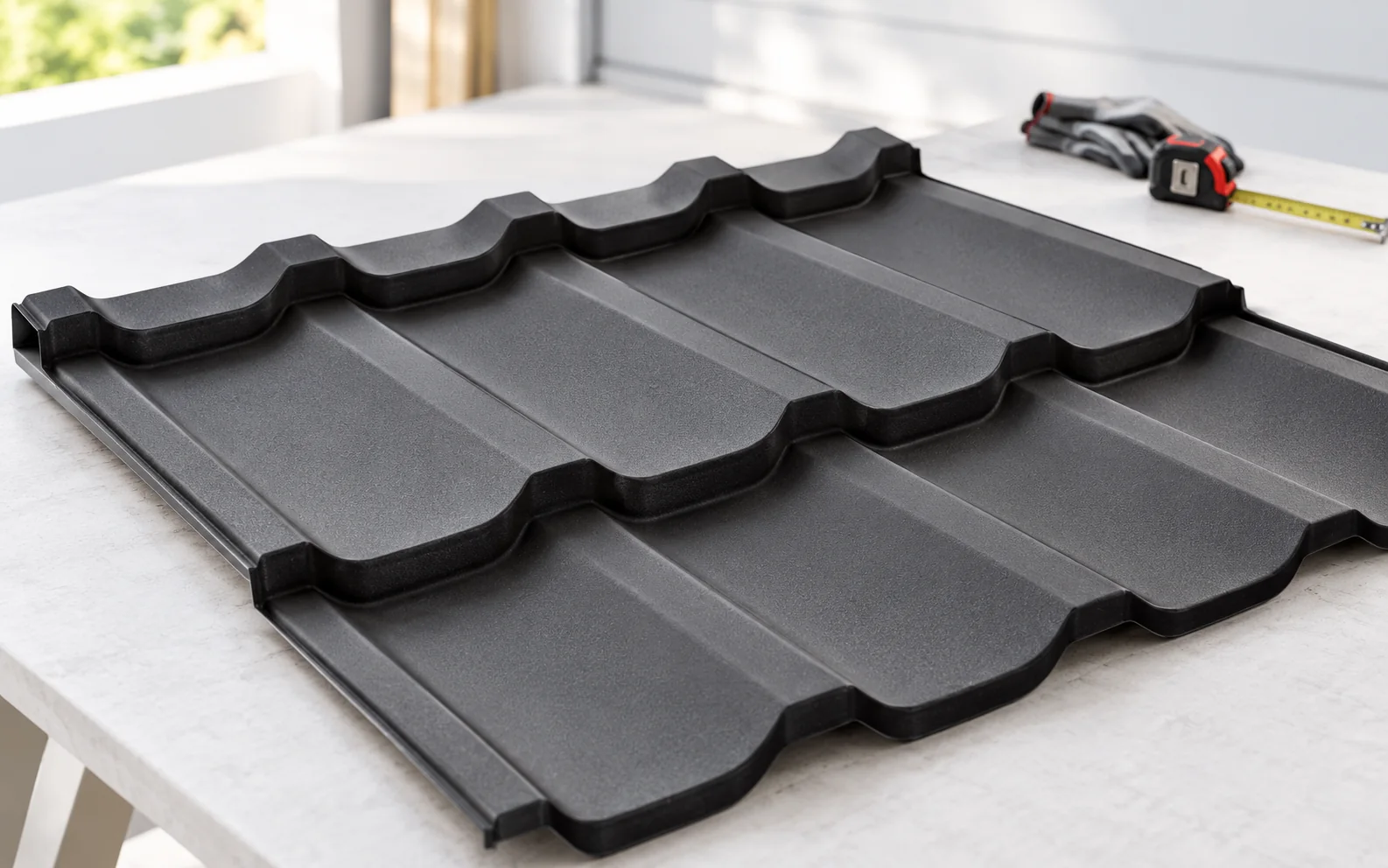
Modular tile-effect metal roofing combines a tile profile with a smaller, repeatable panel format. It can make transport and the organisation of…