How the IKO enertherm ALU TG joint affects insulation continuity

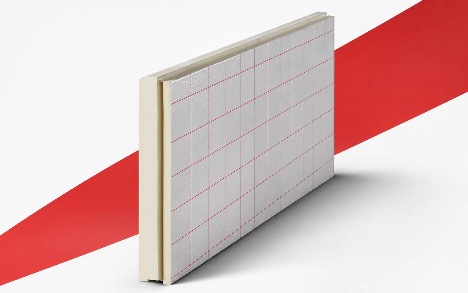
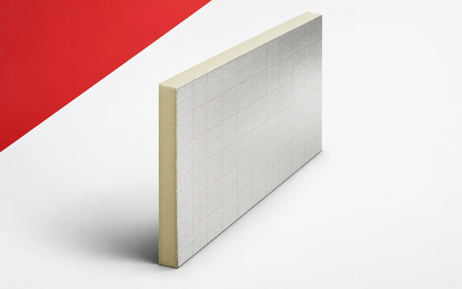
After ALU TG has been laid, the regular field looks tight. At the perimeter, however, cut pieces without the full factory profile appear. It is precisely this strip that may require additional attention when the aim is to limit losses. A good result in the middle of the surface should not be taken as proof that every termination is correct. The starting point is insulation joined by a factory tongue and groove. Here the particular limitation is the absence of the factory profile at the edges after cutting. The design must allow full boards and cut pieces to be joined without gaps in the layer, not merely fit another sheet. The point requiring attention is the edge of a cut piece without the preserved factory tongue.
By |2026-11-15T01:59:33+01:002026-11-15|Expert guides|Comments Off on How the IKO enertherm ALU TG joint affects insulation continuity

Using IKO enertherm ALU data to calculate thermal performance

For a building element with IKO ALU, two thicknesses of the same board are analysed. It is worth checking straight away whether increasing the insulation resistance changes the result for the whole building element to the required degree. If a significant thermal bridge remains at the service penetration, simply thickening the field may not resolve the main limitation. The balance should cover both measures. The starting point is a building element build-up with aluminium-faced PIR boards. Here the particular limitation is the condition that the facing and edges are compatible with the adopted building element. The design is intended to make use of the board's resistance without disregarding the conditions of use for the whole system, rather than merely accommodating another sheet. The point requiring attention is the service penetration through the continuous insulation layer.

By |2026-11-15T01:59:32+01:002026-11-15|Expert guides|Comments Off on Using IKO enertherm ALU data to calculate thermal performance

BauderPIR FA beneath rooftop equipment: insulation continuity and bearing pressure

An installation on an insulated roof needs durable support. The client is concerned about interrupting the thermal layer and proposes leaving the base solely on the PIR. The mere wish to reduce the thermal bridge does not confirm that this decision is correct. In the FA solution, thermal requirements must be matched by calculation of compressive stress and deformation. The starting point is a roof with an installation resting on the layers above the insulation. Here the particular constraint is the actual size of the load-transferring area. The design must allow insulation performance to be combined with permissible deformation under load, not merely accommodate another sheet. The point requiring attention is the bearing area of the rooftop installation's foot. A support drawing will be needed showing the load path and protection of the covering, because a view of the flat area alone does not show all the heights.

By |2026-11-15T01:59:30+01:002026-11-15|Expert guides|Comments Off on BauderPIR FA beneath rooftop equipment: insulation continuity and bearing pressure

How BauderPIR T tapered insulation affects heat loss across a roof

The roof is to receive new falls and better thermal insulation. A BauderPIR T design should combine both tasks in a single system. It is not enough to calculate the thickness of the taper at the highest corner. The distribution of material along the entire drainage path and the thermal performance of all areas must be checked. The starting point is a roof with uncoated tapered boards. Here the particular constraint is correctly assigning each taper to its position in the plan. The design is meant to achieve the required drainage path and a correct thermal section, not merely to fit in another board. The point requiring attention is the valley carrying water towards the outlet. A falls drawing showing the direction of increasing thickness will be needed, because a view of the flat field alone does not show all the heights.

By |2026-11-15T01:59:28+01:002026-11-15|Expert guides|Comments Off on How BauderPIR T tapered insulation affects heat loss across a roof

Choosing BauderPIR M or MF takes more than a lambda value of 0.022

The same PIR thickness appears in two quotes, but one board has an aluminium facing and the other a mineral fleece. The prices look similar, so the difference in parameters is easily overlooked. In the M/MF variant, you have to go back to the correct lambda. Only then will the comparison show whether both proposals provide a similar thermal resistance at the same thickness. The starting point is a roof with a PIR board with a mineral facing. Here a particular constraint is the requirement that the mineral facing be compatible with the adopted system. The design must establish the correct lambda and a compatible connection to the waterproofing, not merely fit in another sheet. The area requiring attention is the fleece zone beneath the waterproofing layer.

By |2026-11-15T01:59:19+01:002026-11-15|Expert guides|Comments Off on Choosing BauderPIR M or MF takes more than a lambda value of 0.022

Choosing BauderPIR FA-TE thickness at a low terrace threshold

For a terrace above a heated room, the threshold height limits the available build-up. The client wants to improve thermal performance without changing the doors. FA-TE can only be considered once all the terrace layers have been set out. The space available for the PIR itself is not the same as the distance from the structure to the finished surface. The starting point is the insulation of the terrace above the room. Here the particular constraint is the height limit below the threshold with the required finish. The design must allow the insulation to fit together with drainage and the terrace finish layers, not merely fit another board. The point requiring attention is the patio door threshold and the nearby drain. A terrace section at the doors with marked levels will be needed, because a view of the flat field alone does not show all the heights.

By |2026-11-15T01:59:17+01:002026-11-15|Expert guides|Comments Off on Choosing BauderPIR FA-TE thickness at a low terrace threshold

BauderPIR FA for continuous roof insulation with high thermal resistance

On a rectangular roof area, the large FA format makes it easier to plan a regular layout. The thermal effect, however, depends on how the boards are used together with their rebates. An underestimated number of boards can lead to improvised infill at the end of the work. A correct quantity take-off is therefore part of planning a continuous insulation layer, not merely a stock calculation. The starting point is the insulation of a large, regular roof area. Here the particular limitation is the loss of covering area caused by the rebate. The design must allow the roof area to be covered while correctly accounting for rebates and cut-offs, not merely fit another board. The point requiring attention is the milled edge of the large-format board. A row plan based on the effective board dimension will be needed, because the view of a flat field alone does not show all the heights.

By |2026-11-15T01:59:16+01:002026-11-15|Expert guides|Comments Off on BauderPIR FA for continuous roof insulation with high thermal resistance

Where roof details interrupt insulation with SOPREMA PIR boards

In the example roof, EFYOS BLUE A has already been installed at the correct thickness, but the vapour control layer has been left with an unresolved termination at the rooflight. The client asks whether another layer of PIR will improve the situation. First, the loss through conduction must be separated from the effects of a leaky junction. These are two problems requiring different measures. The starting point is a complete roof with vapour control layer, insulation and covering. Here, a particular constraint is access to the seal after the subsequent layers have been laid. The design must allow thermal continuity, airtightness and rain protection to be maintained separately, rather than merely accommodating another board. The point requiring attention is the junction between the vapour control layer and the rooflight upstand.

By |2026-11-15T01:59:14+01:002026-11-15|Expert guides|Comments Off on Where roof details interrupt insulation with SOPREMA PIR boards

SOPREMA EFIGREEN ITE for walls with limited insulation depth

On the external wall, the main field allows the full insulation thickness to be accommodated. The difficulty only arises at the narrow reveal and the metal cladding bracket. For EFIGREEN ITE, the energy analysis should cover both locations. Adding material over a large area does not automatically eliminate a local heat flow path. The starting point is external wall insulation with a façade cladding. Here the particular constraint is the space limit at the window reveal and beneath the cladding. The design should allow the insulation to remain continuous without clashing with the window finish, rather than merely accommodating another board. The location requiring attention is the external window reveal and the adjacent façade bracket.

By |2026-11-15T01:59:13+01:002026-11-15|Expert guides|Comments Off on SOPREMA EFIGREEN ITE for walls with limited insulation depth

EFIGREEN ALU+ and PIR board thickness: what difference does thermal conductivity make?

The designer has a thin ALU+ layer and a thicker variant from the same family to compare. At first glance they differ only in thickness. In the stated range, however, lambda also changes. The comparison should therefore use two appropriate data points, not one parameter copied across the whole catalogue. The starting point is the insulation of a roof slope divided by numerous service penetrations. Here the particular constraint is the proportion of short offcuts around obstacles. The design should make it possible to combine the correct thermal parameter with a sensible board layout, not merely to fit in another sheet. The area requiring attention is the narrow field between two service bases.

By |2026-11-14T22:00:37+01:002026-11-14|Expert guides|Comments Off on EFIGREEN ALU+ and PIR board thickness: what difference does thermal conductivity make?
Back to top